Projets:Lab:2015:SolderStation:BoxingEnglish

From Electrolab
Revision as of 09:51, 14 July 2015 by Marc (Talk | contribs)

(diff) ← Older revision | Latest revision (diff) | Newer revision → (diff)
Jump to: navigation, search

A 3D printed casing for the solderstation

This 3D printed box has been created by Alexandre, with FreeCAD and it's 3D "Prussa 3i" for the very first prototypes. This case is made of 2 half-shell, one for the frontplate, the other one for the rear plate. This casing has not been developed to include a power supply (an external 12Vcc power adapter must be supplied by the user itself)

The frontplate supports


  • The display pcb with it's shaft encoder
  • The output connector (soldering ironà
  • The 12Vcc power input connector

The back plane maintains the MCU pcb only

Each board is maintained to it's half-shell with self-tapping screw (6.5mm long, 3mm dia)

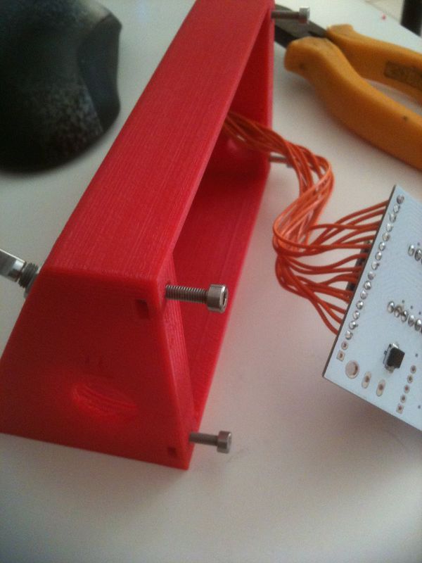
Half-shell are held together with M3 screw and nuts
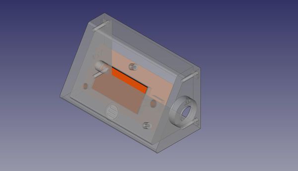
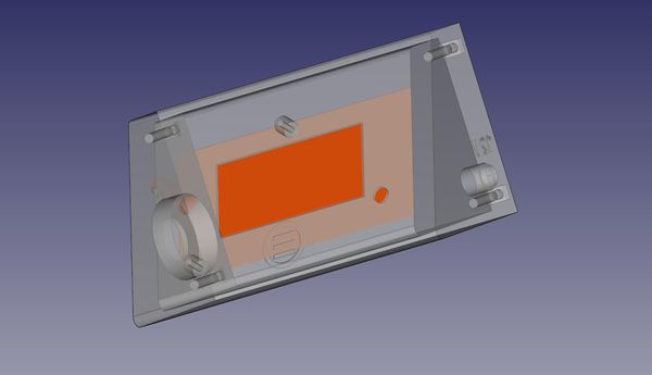
3D modeling of the frontplate under FreeCAD (click on the picture for higher resolution)
3D modeling of the frontplate under FreeCAD: Rear view vue (click on the picture for higher resolution)
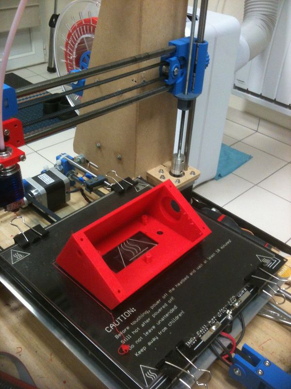
Printing the front plate with the Prusa i3
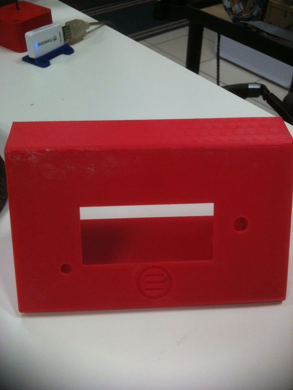
The frontplate is ready to receive it's "payload"
The display board sits on it's supports
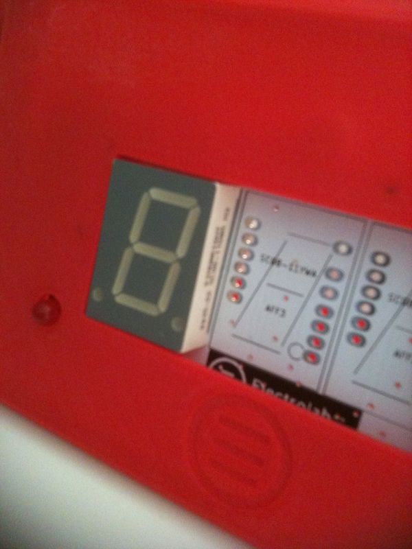
A closer look : the surface of each 7 segment display must flush with the frontplate
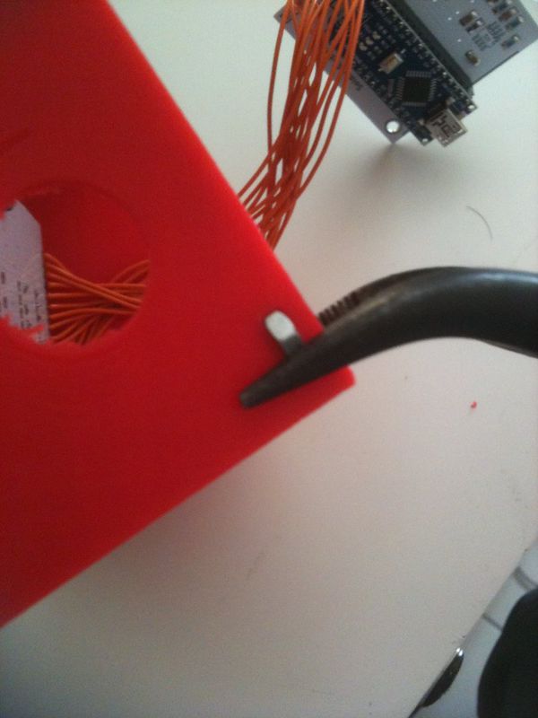
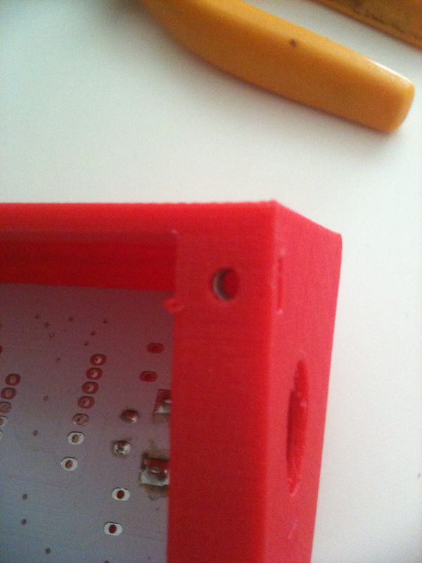
Inserting an M3 nut in it's housing
Use a plier and firmly push on the nut to insert it into it's place
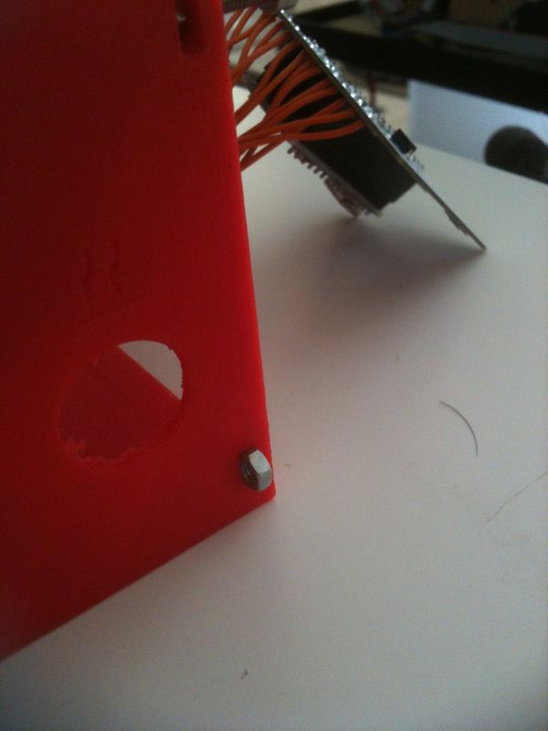
The nut is in position
You should be able to see the thread of the nut through the hole)
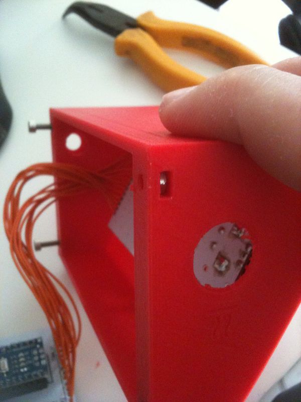
you should not need any effort to tighten the screw
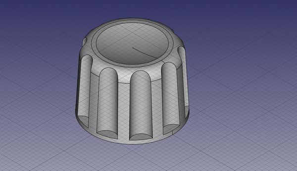
3D modeling of the temperature adjustment knob
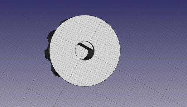
Inside view of the "D Shape" of the knob
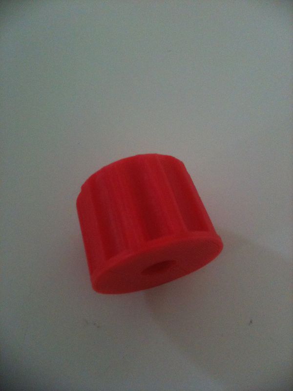
A printed adjustment knob
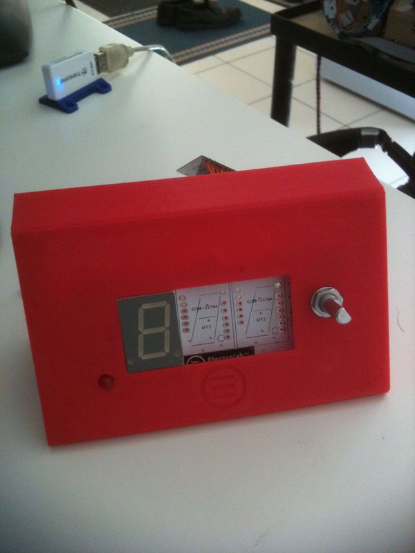
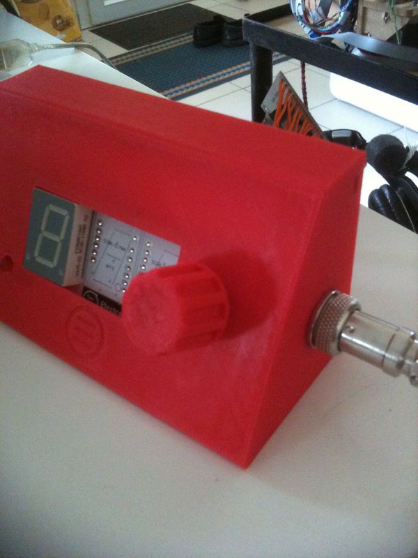
Final and complete assembly of the frontplate, with the "Aviation" connector on the right side