Projets:Perso:2012:StickArcade
| Stick Arcade 2 Players (For Mame) | |
|---|---|
| Auteur | Jnat |
| Date de proposition | 20/02/2012 |
| Tags du projet | Arcade;mame;usbhid;arduino;shift register; |
| Lieu d'utilisation final | @Work/Home |
| Utilisateur final | Gamers! |
| Type de projet
Projet personnel de Jnat | |
|
Overview
This project is about making a working, robust but "cheap" arcade stick. The stick is to be plugged in USB to a computer in order to play Mame arcade emulator or other games.
This project is made of 3 parts:
- Input multiplexing modules : making it possible for a simple arduino or Atmega chip to hold 30+ almost simultaneous inputs from players
- USB HID Module : The device will create 2 gamepad HID and a keyboard HID on host computer
- Stick body : mainly wood/metalworking in order to get a sturdy case (the arcade stick has to be strong and durable)
Input Multiplexing
Since I am using an Arduino diecimila, there is not enough I/o pins to manage 30 input buttons. So multiplexing is needed to make it all fit in.
The multiplexing part is designed to be modular.
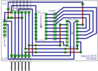
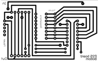
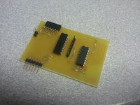
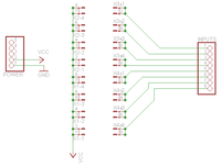
- Each board is based on a 74hc165N PISO shift register.
- Pull up resistors are made with a 8* 9Kohm resistor array but can be replaced by equivalent (or whatever) simple resistors
- These chips can be daisy chained giving a good opportunity to think about scalability.
- A module handles 8 inputs and uses 4 wires of the arduino (+ power and ground).
Status : In Progress
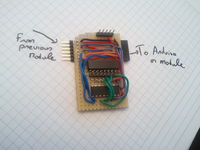
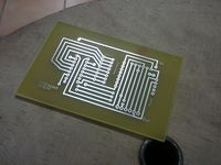
The first module has been soldered and tested
| Task | Status |
|---|---|
| Prototype a working module | Done |
| Make a "real" module | Done |
| Test daisy chain-ability | Done (proto+clean) |
| Connect at least 2 "clean" modules | TODO |
| Improve stability when modules are chained | TODO |
| Module is compact and routing is elegant | TODO |
Toggling an input on is made by connecting +5v to an input pin.
Connector Board
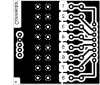
The connector board is designed to sit on top of the input module, making it easy for buttons to be connected via Faston connectors.
- This board is powered by the +5v of the bottom board
- It presents
- 8 power connectors (faston)
- 8 labelled input connectors (faston)
CAUTION : Spacing between header pins may not be consistent with the input module. I need to check this
| Task | Status |
|---|---|
| Prototype | Done |
| Make a "real" module | TODO |
| Test real module | TODO |
USB HID
Todo
